A few days ago I got my latest parcel from Hace electronics an order I had made for Christmas. Inside were three HACEduino Nano's with an ATmega328 on them, I carefully unpacked the package and got a bit of a surprise, Adrian had upgraded my breadboards as he had said he would, but the boards I got were much bigger then I had expected.
As well as the nano's and breadboards there were three complimentary USB cables to program the Haceduino Nanos's and three protoshields (Ver B) to build a project on to. I have wrapped them all up and placed them under the tree, I did solder one of the protoshields together so the kids can copy it on Christmas day.
I did have a look at one idea I have had about using the protoshield as a mounting board to prototype for the HACEduino nano, so far it looks like the concept is sound now I just have to play with it on christmas day and then I will blog about it and will also have some photos for you.
Have a great festive season.
Showing posts with label diy. Show all posts
Showing posts with label diy. Show all posts
Thursday, December 3, 2009


Monday, November 30, 2009
MIcks latest valve project
Well Mick has been up to it again, he has been fiddling with bits and pieces of electronics and has come up with an amp for his guitar. I will leave it to him to describe it in more depth as it is pretty out there.
Specifications for the HACEduino 2009 (Arduino Duemilanove clone)

The HACEduino "2009/328" is a powerful development board based on the ATMEL ATmega328P-PU AVR micro controller, and is still FULLY compatible with the Arduino Duemilanove and its shields, so basically it is an Arduino clone
.
When you purchase a HACEduino "2009/328" you will get a board with a small micro controller, this is a whole computer on a small chip, in this case it is an ATMEL AVR ATMega328P-PU.
The HACEduino's design is quite simple, and its design was intended so as the micro controller could easily communicate with a variety of devices, and could be programmed with your computer with a simple design IDE or Integrated Design Environment without the need for sophisticated hardware to program it. In fact, the software, your HACEduino and a handful of components are all that you need to get started.
A standard HACEduino "2009/328" features 14 Digital I/O pins, These can be inputs or outputs, which is specified by the program, known as a sketch which you create in the IDE. The HACEduino also has 6 Analogue In pins, These dedicated analogue input pins take analogue values (0-5v), for example voltage readings from a sensor and convert them into a number between 0 and 1023.
There are also 6 PWM (pulse width modulation) Output pins, These are six of the digital pins that can be reprogrammed for PWM output using the sketch you create in the IDE, the PWM output allows you to create pseudo analogue output voltages(0-5v)
The HACEduino can be powered from your computer's USB port, a USB charger, or an AC adapter. If using an AC adaptor then a 9 volt one is recommended, it will need to have a 2.1mm barrel tip, centre positive to use the powers socket although you can also connect to the Vin pin on the HACEduino.
If there is no power supply plugged into the power socket or the Vin pin then the power will come from the USB socket, however as soon as you plug a power supply in to the HACEduino it will automatically switch over and use it.
When operating the board with an input voltage between 12V and 14V excessive heat generated by the voltage regulator may damge it. Damage caused by this is not covered by the warranty you get on the HACEduino.
The HACEduino with the ATmega328 micro controller is the perfect entry point to learning to program a micro controller and develop using the Arduino development framework.
The HACEduino "2009/328" has the following features:
| Micro controller ATmega328 |
| Operating Voltage 5V |
| Input Voltage (recommended 9 volts) 7-14V |
| Digital I/O Pins 14 (of which 6 provide PWM output) |
| Analogue Input Pins 6 |
| DC Current per I/O Pin 40 mA |
| DC Current for 3.3V Pin 50 mA |
| Flash Memory 32 KB (ATmega328) 2 KB used by boot loader |
| SRAM 2 KB (ATmega328) |
| EEPROM 1 KB (ATmega328) |
| Clock Speed 16MHz |
Wednesday, November 18, 2009
Motorjet to startTurbojet
G'day All,
it's been a while but I'm back!
(too many Projects, too little money)
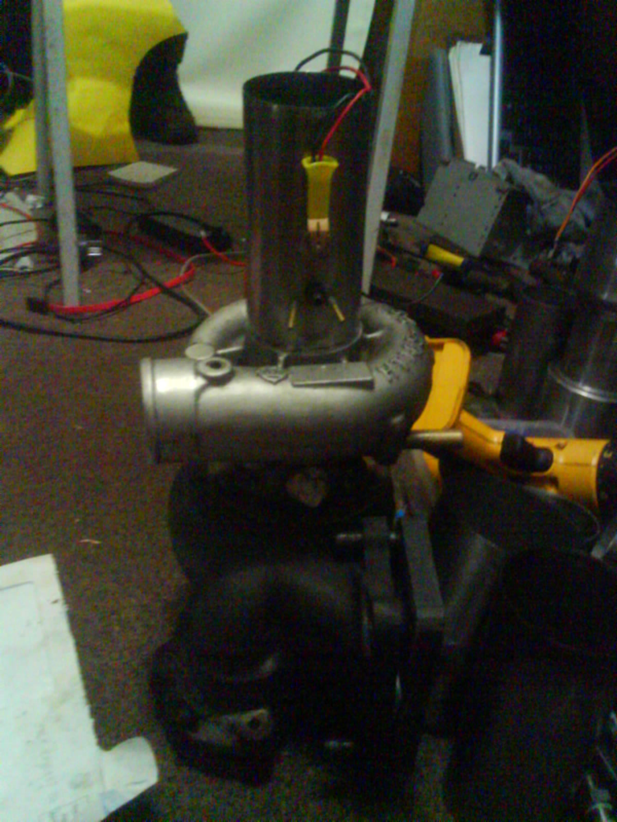
Iv'e been working on a Starter Motor for the Turbo Jet project,
I don't know weather you can make it out from the pix but it's a Cox .049 ci
with a puta fan blade attached!
(yes Brad it IS the same motor I used on the model boats we made as teenagers!)
Appearntly people tried using puta fans as ducted fans in the early days but,
found them to be useless cos the crappy plastics they were made of used to
fly apart when exposed to 22,000 + rpm
(I wonder why?)

But thankfully puta fans now are made out of tough ABS plastic,
which should be up to the task!
Some of the better quality fans are actually balanced!
(you can see the dremel marks on some the back of the blades!)
Cox went out of buisness in Feb 2009 but Iv'e found a shop
in Canada that has a warehouse full of motors and parts!
(and he does bulk lots too! I bought 6 piston/conrod/cylnder assys for
less than 30 bucks au, including postage!)

You can still get the parts to make a replica "Black Widdow Venom"
(the originals were only a run of a 1000 and are very rare!)
BTW, FYI, the "Black Widdow Venom's" were the motors that could pull
22,000 revs!

I have yet to fabricate a bracket to mount the
motor in the "Duct" but as you can see it basicaly
fell together, just drill a few holes in some Stainless Steel tube and Vioal!
A home brew Ducted Fan,
the stainless came from the inside of a "Thermal Cup"
and is quite lightweight and a perfect fit to the Turbo Inlet.
(just dumb luck!)
The motor in the pix is also rare for other reasons,
it is a single transfer port bore which were discontinued early on cos
they only pulled a measly 10,000 to 12,000 to revs!
The more common one comes
with 2 transfer ports and "Slit Exhausts" they pulled from 15,000 to
17,000 revs!
And the Venom's piston was lightened, polished crankshaft, they had
extra ports and had higher compression
they were capable of 22,000 revs

The Idea is use a drill to start the Cox motor then plug the Cox into
the turbo's inlet to start the Turbo Jet!
Cool huh?
BTW,
Ducted Fans actually qualify as a Jet by themself and are also known as Cold Jet's ,
Motor Jets or (my personal favorite) Piston Jets!
cheers, Mick. '-))
Lord,
if you can't make me a better Boy,
don't worry about it,
I'm having a great time as it is!
it's been a while but I'm back!
(too many Projects, too little money)
Iv'e been working on a Starter Motor for the Turbo Jet project,
I don't know weather you can make it out from the pix but it's a Cox .049 ci
with a puta fan blade attached!
(yes Brad it IS the same motor I used on the model boats we made as teenagers!)
Appearntly people tried using puta fans as ducted fans in the early days but,
found them to be useless cos the crappy plastics they were made of used to
fly apart when exposed to 22,000 + rpm
(I wonder why?)

But thankfully puta fans now are made out of tough ABS plastic,
which should be up to the task!
Some of the better quality fans are actually balanced!
(you can see the dremel marks on some the back of the blades!)
Cox went out of buisness in Feb 2009 but Iv'e found a shop
in Canada that has a warehouse full of motors and parts!
(and he does bulk lots too! I bought 6 piston/conrod/cylnder assys for
less than 30 bucks au, including postage!)

You can still get the parts to make a replica "Black Widdow Venom"
(the originals were only a run of a 1000 and are very rare!)
BTW, FYI, the "Black Widdow Venom's" were the motors that could pull
22,000 revs!

I have yet to fabricate a bracket to mount the
motor in the "Duct" but as you can see it basicaly
fell together, just drill a few holes in some Stainless Steel tube and Vioal!
A home brew Ducted Fan,
the stainless came from the inside of a "Thermal Cup"
and is quite lightweight and a perfect fit to the Turbo Inlet.
(just dumb luck!)
The motor in the pix is also rare for other reasons,
it is a single transfer port bore which were discontinued early on cos
they only pulled a measly 10,000 to 12,000 to revs!
The more common one comes
with 2 transfer ports and "Slit Exhausts" they pulled from 15,000 to
17,000 revs!
And the Venom's piston was lightened, polished crankshaft, they had
extra ports and had higher compression
they were capable of 22,000 revs

The Idea is use a drill to start the Cox motor then plug the Cox into
the turbo's inlet to start the Turbo Jet!
Cool huh?
BTW,
Ducted Fans actually qualify as a Jet by themself and are also known as Cold Jet's ,
Motor Jets or (my personal favorite) Piston Jets!
cheers, Mick. '-))
Lord,
if you can't make me a better Boy,
don't worry about it,
I'm having a great time as it is!
Creating A Linux Arduino Development Enviroment
I started playing with my haceduino 2009 and couldn't get it to upload sketches to my board, I played for a while trying to hit the reset switch at different times but with no luck.
I hooked the board up to a windows machine and had it uploading almost right away so this led me to my Linux machine being at fault. What to do, what to do....
So last night I played with a few different Linux distros to find one that works "right out of the box" so to speak. It had to be a mainstream distro, had to be a clean install and only need packages available from the repos so as not to have to revert to compiling from source.
This guide is to set up a machine from scratch with the latest Ubuntu release 9.10, it should work with kubuntu and xubuntu as well but I offer no warranty as to the sutablity of this guide to your own hardware and setup
I hooked the board up to a windows machine and had it uploading almost right away so this led me to my Linux machine being at fault. What to do, what to do....
So last night I played with a few different Linux distros to find one that works "right out of the box" so to speak. It had to be a mainstream distro, had to be a clean install and only need packages available from the repos so as not to have to revert to compiling from source.
This guide is to set up a machine from scratch with the latest Ubuntu release 9.10, it should work with kubuntu and xubuntu as well but I offer no warranty as to the sutablity of this guide to your own hardware and setup
INSTALLING ARDUINO IDE FOR THE HACEDUINO 2009 ATmega328 UNDER UBUNTU KARMIC KOALA
Do a fresh install of Ubuntu Karmic Koala 9.10
At the command line perform the following commands to prepare your system for the arduino IDE.
- sudo apt-get update (Update Package list)
- sudo apt-get upgrade (Upgrade all installed packages)
- sudo apt-get remove brltty (Remove as it conflicts when uploading sketches)
- sudo apt-get install sun-java6-jre avrdude gcc-avr avr-libc ftdi-eeprom (Install dependencies for the Arduino IDE)
- cd ~/ (change to your home directory)
- wget http://arduino.googlecode.com/files/arduino-0017.tgz (Download IDE from googlecode)
- tar xzvf arduino-0017.tgz (extract files from the archive)
- sudo reboot (reboots the machine)
- Plug your Haceduino in to a USB port and wait 10 seconds for it to connect
- To run the IDE you need to exucute the file ~/arduino-0017/arduino this will launch the IDE
- Go to tools/board/arduino and select Duemilanove or Nano w/ ATmega328
- Go to tools/serial port/devttyUSBx (Select the port your board is plugged in to)
- Load a sketch from the examples choices, the file/digital/blink is a good start to make sure it is working as it doesnt require any additional hardware apart from the haceduino and a USB cable
- Click on the upload button second icon from the right at the top of the IDE and the sketch should compile and be uploaded to the Haceduino 2009, the red and green serial traffic LEDs should flash for a few seconds
- You should now have an orange LED blinking on the haceduino that is different to the dit dit dah flash that was all ready on the haceduino.
- By playing with the values in the sketch you should be able to make it blink faster or slower, why don't you have a try now.
Saturday, November 14, 2009
Waiting on my first HACEduino
I just brought an HACEduino it is a arduino compatible on ebay, It was only AUD 31.50 and that included free postage. I found some code to make it talk to a nokia S60 phone running python (my N97 has python installed)
I am thinking of setting it up to start the motorbike remotely that would be cool
I am thinking of setting it up to start the motorbike remotely that would be cool
Sunday, November 8, 2009
Acer Aspire One Wont boot
Sometimes when switching on an Acer Aspire One it shows a black screen. The LEDs may be blinking or just the power button led may be on, and usually the fan is turning. But the screen remains black.
This is a known problem on the Aspire one and is a BIOS fault, fortunately the Acer Aspire One has a BIOS recovery procedure that makes it possible to reflash the BIOS even when the Aspire one wont boot anymore.
This procedure is only meant for non booting Aspire one's and may void the warranty on the unit, so please follow this guide as a last resort.
Format a USB memory stick to FAT16. (It doesnt have to be a big memory stick)
Head over to Acer and download the BIOS files from the support website:
Aspire One Model A150 or Aspire One Model A110
Extract the files and put FLASHIT.EXE and the BIOS files in the root directory of the memory stick.
Rename the BIOS file to ZG5IA32.FD
Make sure to insert a charged battery and connect the AC supply.
Insert the USB Memory stick into a USB port on the Aspire One.
Press the Fn+Esc keys keep them pressed and press the power button to turn the AA1 on.
Release Fn+Esc after a few seconds, the power button will now be blinking.
Next press the power button once,. The Aspire one will now preform the BIOS flash, under no circumstances should you stop this process. After a few minutes the power button LED should stop blinking, and shortly later the Aspire One will preform a reboot.
All going well the BIOS is now flashed and all the settings will be reset to default in the BIOS
This is a known problem on the Aspire one and is a BIOS fault, fortunately the Acer Aspire One has a BIOS recovery procedure that makes it possible to reflash the BIOS even when the Aspire one wont boot anymore.
This procedure is only meant for non booting Aspire one's and may void the warranty on the unit, so please follow this guide as a last resort.
Format a USB memory stick to FAT16. (It doesnt have to be a big memory stick)
Head over to Acer and download the BIOS files from the support website:
Aspire One Model A150 or Aspire One Model A110
Extract the files and put FLASHIT.EXE and the BIOS files in the root directory of the memory stick.
Rename the BIOS file to ZG5IA32.FD
Make sure to insert a charged battery and connect the AC supply.
Insert the USB Memory stick into a USB port on the Aspire One.
Press the Fn+Esc keys keep them pressed and press the power button to turn the AA1 on.
Release Fn+Esc after a few seconds, the power button will now be blinking.
Next press the power button once,. The Aspire one will now preform the BIOS flash, under no circumstances should you stop this process. After a few minutes the power button LED should stop blinking, and shortly later the Aspire One will preform a reboot.
All going well the BIOS is now flashed and all the settings will be reset to default in the BIOS
Wednesday, March 18, 2009
My Ramjet
Yo Punters,
it's Mick again,
I've found (and made) a new Jet to play with.
They are a bit quieter than the Pulse jets and
generate an enormous amount of Heat
and consume even more enormous amounts of Fuel!
I've built a Ramjet!
as you can see it's lots of heat, lots of Gas and lots of Fun!
It was simple to make, just a Stainless Steel drinking cup and the inside part of of a Vittorio coffee cup, ( you know the Insulated ones like a thermos.) and then Weld them together!

A tip for those of you who may want to make one of these is,
make the Inlet about half of the diameter of the outlet,
mine is about the same size inlet as the outlet and I think that is why it is so fuel hungry!
 Well that's another post over and done with,
cheers, Mick. '-))
it's Mick again,
I've found (and made) a new Jet to play with.
They are a bit quieter than the Pulse jets and
generate an enormous amount of Heat
and consume even more enormous amounts of Fuel!
I've built a Ramjet!
as you can see it's lots of heat, lots of Gas and lots of Fun!
It was simple to make, just a Stainless Steel drinking cup and the inside part of of a Vittorio coffee cup, ( you know the Insulated ones like a thermos.) and then Weld them together!

A tip for those of you who may want to make one of these is,
make the Inlet about half of the diameter of the outlet,
mine is about the same size inlet as the outlet and I think that is why it is so fuel hungry!
 Well that's another post over and done with,
cheers, Mick. '-))
Friday, August 22, 2008
Shock, Horror Gasp! Dept.
I was playing with my Relay Spark Gap Tesla Coil ( RSGTC )
the other day and I noticed something funny was happening,
I was seeing how low a voltage it would run on so I hooked up a 6 volt SLA and when I checked the supply voltage It was higher than when it was at Idle!
W.T.F.?
Naaah, nah, nah, this is not Right!
I could see the circuit was using power, it was lighting up a flouro!
Must be a flat battery in my D.M.M.,
so I changed the 9 volt and fired it up again.
W.T.F.? again.
.
Hmmmm,
ok hook it up to the 12 volt SLA,
no every thing seems kosher here,
voltage dropping slowly Milli volt by Milli volt.
Ok, try the 13.8 volt Motorcycle battery,
same, same,
ok try hooking the wet cell and SLA together to get 24 volt or so,
impressive but nothing unusual here either.
Last resort a 9 volt ni-cad,
nada, everything cool here too.
Hook the 6 volt up
and it's doin' the weird shit again,
what the hell is going on here!
After much Pondering and Brane stretchin' I think I have an answer!
Back E.M.F.!
Yep, I reckon that explains a heap!
I reckon a relationship exists between the freq. it oscillates at when running @ 6 v., and
possibly the relay coil or maybe the physical construction of the SLA or maybe even both!
It's not quite Over Unity, more like Close to Unity!
It took about 3 days to run down to 5.2 volt at which point the relay could no longer sustain itself!
( not bad for a 12 volt relay!)
This compares to about 3.5 hrs. using the 12 volt 1.2 a/h SLA!
Ah, I hear you say, how many a/h is the 6 volt?
The answer is 6.5 a/h!
so taking the discharge rate of the 12 volt into account we come up with <20 hours!
It will take a better Brane than mine to explain it properly and model it Mathematically but,
I will endeavour to some how optimise a cct to take advantage of this anomaly,
you never know,
they say the greatest discoveries started out as mistakes!
cheers,
Mick. ;-))
I was playing with my Relay Spark Gap Tesla Coil ( RSGTC )
the other day and I noticed something funny was happening,
I was seeing how low a voltage it would run on so I hooked up a 6 volt SLA and when I checked the supply voltage It was higher than when it was at Idle!
W.T.F.?
Naaah, nah, nah, this is not Right!
I could see the circuit was using power, it was lighting up a flouro!
Must be a flat battery in my D.M.M.,
so I changed the 9 volt and fired it up again.
W.T.F.? again.
.
Hmmmm,
ok hook it up to the 12 volt SLA,
no every thing seems kosher here,
voltage dropping slowly Milli volt by Milli volt.
Ok, try the 13.8 volt Motorcycle battery,
same, same,
ok try hooking the wet cell and SLA together to get 24 volt or so,
impressive but nothing unusual here either.
Last resort a 9 volt ni-cad,
nada, everything cool here too.
Hook the 6 volt up
and it's doin' the weird shit again,
what the hell is going on here!
After much Pondering and Brane stretchin' I think I have an answer!
Back E.M.F.!
Yep, I reckon that explains a heap!
I reckon a relationship exists between the freq. it oscillates at when running @ 6 v., and
possibly the relay coil or maybe the physical construction of the SLA or maybe even both!
It's not quite Over Unity, more like Close to Unity!
It took about 3 days to run down to 5.2 volt at which point the relay could no longer sustain itself!
( not bad for a 12 volt relay!)
This compares to about 3.5 hrs. using the 12 volt 1.2 a/h SLA!
Ah, I hear you say, how many a/h is the 6 volt?
The answer is 6.5 a/h!
so taking the discharge rate of the 12 volt into account we come up with <20 hours!
It will take a better Brane than mine to explain it properly and model it Mathematically but,
I will endeavour to some how optimise a cct to take advantage of this anomaly,
you never know,
they say the greatest discoveries started out as mistakes!
cheers,
Mick. ;-))
Mick's Tesla Coil Endevours!
Hi all again,
Firstly the video didn't load in my last post, I dunno why but I'll get Mark to look into it when he is feeling better. (he has a dose of the flu!).
Right said Fred lets go!
I got an idea to use a relay as a spark gap from a site on You tube,
http://www.youtube.com/watch?v=klQCCbEWhRo&NR=1
after watching this vid I freeze framed it to reverse engineer it!
It turned out to comprise only 3 major parts, 4 if you include the battery!

A Relay (configured to be a buzzer),

a capacitor (to Tank the primary),

a battery

and of course a Tesla Coil!

I hooked it up to a Mini Twin Tesla Coil that I was intending to make a solid state driver for!

It's a little pearler
and it worked 1st go too!


I imagine I could get more power out of it if I wound my own buzzer with an adjustable gap!
I did play around with the spring tension in the relay and got some overall improvement!
I got the idea for the twin coil setup from this site!
http://www.sky-chaser.com/tcpart5.htm
I seem to be quite lucky when I'm winding coils,
I used a 1" form and wound an arbitary 4" tall pair of Secondaries!
(using the Hair fine wire I got from the printer relay!)
The Primaries were an arbitary job too @ 4.8 turns each!
Oh and the "tank Cap" is 220 pF @ 1kV
well thats another post all done and dusted,
remember,
"If you always do what you did,
You'll always get what you got!"
Cheers again,
Mick. ;-))
Firstly the video didn't load in my last post, I dunno why but I'll get Mark to look into it when he is feeling better. (he has a dose of the flu!).
Right said Fred lets go!
I got an idea to use a relay as a spark gap from a site on You tube,
http://www.youtube.com/watch?v=klQCCbEWhRo&NR=1
after watching this vid I freeze framed it to reverse engineer it!
It turned out to comprise only 3 major parts, 4 if you include the battery!

A Relay (configured to be a buzzer),

a capacitor (to Tank the primary),

a battery

and of course a Tesla Coil!

I hooked it up to a Mini Twin Tesla Coil that I was intending to make a solid state driver for!

It's a little pearler
and it worked 1st go too!


I imagine I could get more power out of it if I wound my own buzzer with an adjustable gap!
I did play around with the spring tension in the relay and got some overall improvement!
I got the idea for the twin coil setup from this site!
http://www.sky-chaser.com/tcpart5.htm
I seem to be quite lucky when I'm winding coils,
I used a 1" form and wound an arbitary 4" tall pair of Secondaries!
(using the Hair fine wire I got from the printer relay!)
The Primaries were an arbitary job too @ 4.8 turns each!
Oh and the "tank Cap" is 220 pF @ 1kV
well thats another post all done and dusted,
remember,
"If you always do what you did,
You'll always get what you got!"
Cheers again,
Mick. ;-))
Mick's Tesla Coil Endevours!
After pressure from the West and East coast (hi Sean and Mark respectively) of my beloved Oz, (Australia of course)
It seems to be time to document my
"Tesla Coil experiences/endeavours"

so here goes for good or ill!
After my Pulse Jet getting shut down 'cause it was too LOUD,
I had to find something quieter to occupy my brane so,
yet again my muse (Mark) stumbles me a site ,
http://www.plasmatweeter.de/eng_plasma.htm
Ulrich Haumann's Plasma Tweeter site.
And yet another childhood dream is embarked upon as,
I realised that it was a Modulated Tesla Coil of sorts!
I went to my Valve (a.k.a. tube) stash to see if I had anything suitable.
Sadly I deemed nothing came close to the Valve that Ulrich was using to
drive the coil.
I've got plenty of 12AX7's and had just scored a blown up telly from my neighbor Marika
to rat out for parts and, it came complete with` a 1500 volt Hitachi 2SD870 power transistor!
WooHoo!
So its eBay to the rescue!
Sure enough I find and purchase a pair of Svetlana 6P45S's (you gotta love those Russians!)
from a guy in the Czeck Republic!
But while I was waiting for them to arrive, I continued to surf the net and after I had checked out a number of sites I reckoned I might be able to coax the required power out of a 6V6GT, (of which I have 3!) and so my first Tesla Coil was born!
I basically lifted the circuit straight from Jon's Electronixandmore's site,
(see link below)
because the input voltage Jon was using was well within a 6V6GT's limits!
http://www.electronixandmore.com/project/index.html
I wound all the coils by hand (no coil winders for me.......Yet!) to the spec Jon supplied
and just substituted my 6V6GT for his 6146,
the one big difference was I didn't have enough 24 gauge wire to wind the Secondary
so I pulled apart a relay coil out of a printer to get enough wire but it was hair fine more like 35 or 39 gauge!
I continued on anyway and wound the Secondary Coil.
It turned out to be 4" tall instead of 6" but hey it'll work or it wont!
Turns out it did and here it is!
 The little power supply you can see in the right if the pic is the very first Valve project I ever made and still puts in great service all these years later!
(full wave @ 330 V aprox. 250 mA.)

As you can see, I could draw a 1/4" Arc to an insulated screwdriver.
I can now assume the title of "Mad Scientist" and I wear it Proudly!
But as it seems to be with all "Coilers" (I love it!) I had to have MORE POWER!
Hmmmm, those other two 6V6GT's were lazily sitting around doin' nuthin' so they got shanghaied into the project, and were quickly paralelled into the circuit!


Hmmmm, not a great difference but it was a little better but, .........need more!
So I wound another 2 plate (a.k.a. anode) chokes and wired them in,
Hmmmm,...... a little better again but not much.
What to do, what to do, what to do?
While pondering this it was well past time to play with my new toy!
And play I did,
I put a Flouro tube near it and i lit up fully,
Kewl!
What next?
A frosted light globe?
It glowed with a nice purplish glow!
Double Kewl!
Hey Mark have you got any clear light globes?
He certainly did and it was quickly pressed into service!
Unbelievably Kewl!
Plasma Globe!
I was in Mad Scientist heaven,
It works YIPPEEEEEEE!
But still no coronas, hmmm, bummer.
What else have I got that I can light up,
what about a Flouro starter?
So the cover was removed along with the capacitor that was inside and,
it too was pressed into service!
Lo and Behold a vast differance was instantly noticeable,
it was forming two little coronas on the end of the starter wires!
 Without knowing why I seemed to have gained a lot of extra power,
hmmmmmm, ponder, ponder, ponder?
It would seem that the starter was creating a little bit of extra capacitance the secondary coil needed to tune it in properly!
Here is a short vid of my efforts!
In my next post I'll show you my mini twin coil spark gap Tesla Coil!
Cheers for now,
Mick. ;-))
It seems to be time to document my
"Tesla Coil experiences/endeavours"

so here goes for good or ill!
After my Pulse Jet getting shut down 'cause it was too LOUD,
I had to find something quieter to occupy my brane so,
yet again my muse (Mark) stumbles me a site ,
http://www.plasmatweeter.de/eng_plasma.htm
Ulrich Haumann's Plasma Tweeter site.
And yet another childhood dream is embarked upon as,
I realised that it was a Modulated Tesla Coil of sorts!
I went to my Valve (a.k.a. tube) stash to see if I had anything suitable.
Sadly I deemed nothing came close to the Valve that Ulrich was using to
drive the coil.
I've got plenty of 12AX7's and had just scored a blown up telly from my neighbor Marika
to rat out for parts and, it came complete with` a 1500 volt Hitachi 2SD870 power transistor!
WooHoo!
So its eBay to the rescue!
Sure enough I find and purchase a pair of Svetlana 6P45S's (you gotta love those Russians!)
from a guy in the Czeck Republic!
But while I was waiting for them to arrive, I continued to surf the net and after I had checked out a number of sites I reckoned I might be able to coax the required power out of a 6V6GT, (of which I have 3!) and so my first Tesla Coil was born!
I basically lifted the circuit straight from Jon's Electronixandmore's site,
(see link below)
because the input voltage Jon was using was well within a 6V6GT's limits!
http://www.electronixandmore.com/project/index.html
I wound all the coils by hand (no coil winders for me.......Yet!) to the spec Jon supplied
and just substituted my 6V6GT for his 6146,
the one big difference was I didn't have enough 24 gauge wire to wind the Secondary
so I pulled apart a relay coil out of a printer to get enough wire but it was hair fine more like 35 or 39 gauge!
I continued on anyway and wound the Secondary Coil.
It turned out to be 4" tall instead of 6" but hey it'll work or it wont!
Turns out it did and here it is!
 The little power supply you can see in the right if the pic is the very first Valve project I ever made and still puts in great service all these years later!
(full wave @ 330 V aprox. 250 mA.)

As you can see, I could draw a 1/4" Arc to an insulated screwdriver.
I can now assume the title of "Mad Scientist" and I wear it Proudly!
But as it seems to be with all "Coilers" (I love it!) I had to have MORE POWER!
Hmmmm, those other two 6V6GT's were lazily sitting around doin' nuthin' so they got shanghaied into the project, and were quickly paralelled into the circuit!


Hmmmm, not a great difference but it was a little better but, .........need more!
So I wound another 2 plate (a.k.a. anode) chokes and wired them in,
Hmmmm,...... a little better again but not much.
What to do, what to do, what to do?
While pondering this it was well past time to play with my new toy!
And play I did,
I put a Flouro tube near it and i lit up fully,
Kewl!
What next?
A frosted light globe?
It glowed with a nice purplish glow!
Double Kewl!
Hey Mark have you got any clear light globes?
He certainly did and it was quickly pressed into service!
Unbelievably Kewl!
Plasma Globe!
I was in Mad Scientist heaven,
It works YIPPEEEEEEE!
But still no coronas, hmmm, bummer.
What else have I got that I can light up,
what about a Flouro starter?
So the cover was removed along with the capacitor that was inside and,
it too was pressed into service!
Lo and Behold a vast differance was instantly noticeable,
it was forming two little coronas on the end of the starter wires!
 Without knowing why I seemed to have gained a lot of extra power,
hmmmmmm, ponder, ponder, ponder?
It would seem that the starter was creating a little bit of extra capacitance the secondary coil needed to tune it in properly!
Here is a short vid of my efforts!
In my next post I'll show you my mini twin coil spark gap Tesla Coil!
Cheers for now,
Mick. ;-))
Subscribe to:
Posts (Atom)